|
链接:http://www.kongziwen.com/WRIST%20GAMMA%20INDICATOR.htm
WRIST GAMMA INDICATOR РМ1208M OPERATING MANUAL
CONTENTS
1 Introduction ………………………………. .............................................................................. 3 2 DESCRIPTION AND OPERATION OF THE INDICATOR………………………. ..... 4 2.1 Application of the indicator…………………………………………………........................... 4 2.2 Delivery kit..……………………………………............................................................................................ 5 2.3 Specifications……………………………………………………........................................................ 6 2.4 Design and theory of operation ……………………………………………………............ 10 2.5 Marking and package …………………………………………………….................................... 11 3 USE OF THE INDICATOR ………………………. .............................................................. 13 3.1 Preparation for use ………………………………………………….............................................. 13 3.2 Use of the indicator.................................................................................................................................................... 14 4 MAINTENANCE.............................................................................................................................................................. 25 5 TROUBLESHOOTING............................................................................................................................................. 27 6 STORAGE AND SHIPPING................................................................................................................................. 28 7 WARRANTY.......................................................................................................................................................................... 29 1 Introduction This Operating Manual is intended to describe the design, operation and use of wrist gamma indicator PM1208M (hereinafter referred to as indicator). The Operating Manual includes the general description, specifications of the indicator, instructions for the use of the indicator, maintenance recommendations, as well as some other information necessary for the proper operation of the indicator and a full realization of its possibilities. During manufacturing of the indicator some changes may be introduced in its electrical scheme and construction that do not influence the specifications and, therefore, may be not specified in this manual.
2 DESCRIPTION AND OPERATION OF THE INDICATOR
2.1 Application of the indicator 2.1.1 The indicator is designed to provide: - continuous all day registration and indication of the ambient dose equivalent rate of gamma radiation *(10) (hereinafter referred to as DER); - continuous all day registration and indication of the ambient dose equivalent of gamma radiation H*(10) (hereinafter referred to as DE); - measurement of the DE accumulation time of gamma radiation; - use as an electronic watch (indication of current time and date on the digital liquid crystal display (LCD)); - use as an alarm clock; - indication of the time in hours, minutes and seconds on the electronic analogue quartz watch (thereafter referred to as analogue watch); - communications of information accumulated and stored in a non-volatile memory through infra-red (IR) communication channel (the protocol is compatible with IrDA interface) into the personal computer (PC). The indicator may be used to assess the radiation situation and to provide audible alarms in the case of radiation danger (when the threshold values are exceeded), to detect the radioactive contamination sites or to locate the gamma radiation sources and also as a wrist watch. The indicator preserves its capacity for work when it is immersed in water to a depth of 100 m. The indicator is not the measuring device so its readings may not be used for official findings. For proper interpretation of the results obtained using the indicator it is recommended to take advice of local competent institutions. Operating conditions: - ambient air temperature from 0 to plus 45о С; - relative humidity up to 95 % at the temperature plus 40о С.
Table 2.1
2.3 Specifications
2.3.1 DER registration and indication range Intrinsic relative error of DER registration in the range from 0.1 to 9999.99 Sv/h is no more than 2.3.2 DE registration and indication range Intrinsic relative error of DE registration in the range from 0.01 to 9999.999 mSv is no more than 2.3.3 DER threshold range (step) 2.3.4 DE threshold range (step) 2.3.5 Indication range of DE accumulation time (indication step) 2.3.6 The continuous control of the registered DER and DE values relative to the preset threshold (the least division –two segments) from 0.001 to 9999.999 mSv 0.01 - 9999.99 Sv/h (the least significant digit) 0.001 - 9999.999 mSv (the least significant digit) 1-9999 h 1 h Representation of the result on the linear and circular graphic scales (0.1 of the preset threshold level) 2.3.7 The energy range of the registered from 0.06 to 1.5 MeV gamma radiation 2.3.8 Additional relative error of DER and DE registration: - at ambient temperature variation from normal to 0 °С and from normal to 45 °С - at relative humidity of ambient air 95 % at the temperature plus 40 °С - at power voltage variations from nominal value to limiting voltage values - under the influence of radio frequency electromagnetic fields up to 10 V/m 5 % 5 % 5 % 15 % 6
2.3.9 Indication, setting and adjustment of the current time and date
The accuracy of the electronic watch under the normal conditions no less than The accuracy of the analogue watch under the normal conditions no less than hours (24); minutes; seconds; date, month’s number, year 0,5 s 1 s 2.3.10 The indicator may be used as an alarm clock with an audible signal sounded during one minute at the set time with a period of 24 hours 2.3.11 The indicator provides the recording in history about 500 of DER and DE values with programmable time interval related to the time and date preset on the display. The interval of the events' recording in history: - at recording the final number of events - from 1s to 99 h 59 min 59 s; - at circular recording the events - from 1min to 99 h 59 min 59 s; - time interval before the recording of the first event of the history - from 1s to 99 h 59 min 59 s; 2.3.12 The information exchange with PC – IrDA compatible protocol of communication with PC. In PC communication mode the indicator provides the following functions: 1) enable or disable (switch on/off) of the additional operating mode of indicator: - the mode of DER registration start and recording in memory of DER value; 2) read-out of the following information from the indicator to PC : - indicator serial number; - alarm clock time; - values of the preset DE and DER thresholds; - interval of DER and DE history recording; - time interval before the recording of the first event of DER and DE history; - DE and DER history (date, time, event, value) in accordance with the preset step of history recording; - DE and DER history (date, time, event, value) at the moment of manual history recording; - DE and DER history (date, time, event, value) at the moment of exceeding the preset thresholds for DE and DER; - DE and DER history (date, time, event, value) at the moment of setting the new time zone at electronic watch; 7
3) recording of the following information from PC to indicator: - the PC current time and date;
- alarm clock time; - values of DE and DER thresholds; - interval of DER and DE history recording: - time interval before the recording of the first event of DER and DE history; - the reset of the accumulated DE and the time of DE accumulation. 2.3.13 Period of continuous operation of the indicator from one battery (CR2032, 210 mAh) - no less than 18 months provided that the following operating conditions are observed: - average registered DER value is no more than 0.2 Sv/h; - backlight is used for no longer than 3 s/24 hours; - audible signals sound is used no longer than 20 s/24 hours. Two-level control of the battery voltage: - the partial battery discharge (flashing message “bAtt”); - the critical battery discharge (non-flashing message “bAtt”) 2.3.14 The indicator is supplied with a display backlight, which is turned ON when button 3 (LIGHT) is pressed (see Fig.2.1). 2.3.15 The case of the indicator provides: - the degree of protection IP68; - protection from water penetration when the indicator is immersed in water to a depth of 100 m*) for a short-time period; 2.3.16 The indicator is resistant to: - air temperature from 0 to plus 45о С ; - relative air humidity up to 95% at 40о С . 2.3.17 The indicator is resistant to: - sinusoidal vibration within a frequency range from 5 to 35 Hz and bias amplitude 0.75 mm for frequencies lower than the transition frequency; - shocks with an acceleration of 100 m/s2, a shock pulse duration 2-50 ms and a rate 60-180 shocks per minute 8
2.3.20 The indicator in a transport package is proof against the action of: - air temperature from minus 50о С to plus 50о С ; - air humidity up to 100% at 40оС; - shocks with an acceleration of 98 m/s2, a shock pulse duration 16 ms; - sinusoidal vibration within a frequency range 10-55 Hz and the bias amplitude 0.35 mm
*) Attention! - The indicator can be immersed in water to a depth of 100 m for a short-time period. At the water-immersion of the indicator it is not allowed to press the control buttons and set the time of electronic and mechanical watch. 9
2.4 Design and theory of operation
2.4.1 A Geiger-Muller tube, which converts gamma radiation quanta to electric pulses that are processed by the microprocessor is used as gamma radiation detector. The microprocessor controls the operation modes of the indicator (excepting for the analogue watch movement), electronic watch, information processing, storage and indication of and self-testing. A graduation direction and the indicator effective center relative to which the factory calibration is performed are shown in Fig.2.1. The algorithm of the indicator work provides a continuous registration of DER and DE of gamma radiation, the necessary statistical processing of the results and their adequate indication on the liquid crystal display (LCD), a fast adaptation to variations of gamma radiation DER, setting of the response time in inverse dependence on the DER. The DER and DE measurements are carried out continuously and are independent on a value indicated at the moment on LCD. The indicator allows setting the DER and DE threshold levels. An excess of the preset threshold levels may be controlled audibly or visually on LCD. 2.4.2 The indicator is designed as a wrist watch and includes an electronic block of registration and a movement of analogue watch. The total surface density of the indicator front and side walls enclosing the detector is 1 g/cm2 that provides the indicator protection from the background beta radiation. The indicator is supplied with an electro luminescent backlight of LCD. The hands of the analogue watch are located above the LCD of the indicator. Four buttons to control the electronic block of registration and a crown to control the movement of the analogue watch are located around the periphery of the indicator case (Fig.2.1). To restart the microprocessor operation, a special button is used which is flush-mounted to avoid its accidental pressing. The controls and indication elements (Fig. 2.1) are as follows: 1 - MODE, the button is used to switch between the indicated values: - DER indication, - DE indication, - current time indication, as well as to change the parameters, to switch ON/OFF the alarm clock and the dose rate audible indication, to start registration in the DER mode and to store the DER values. 2 - SELECT. The button is used to enter the reference mode or to exit it: to check the alarm clock ON time; date and month, year, minutes and seconds; to enter the set mode and exit from it, as well as to enter and exit the data storage mode, DER registration start mode and the PC communication mode. N o t e - Buttons 1(MODE) and 2 (SELECT) are used in two ways: pressing (for approximately 1 s) and releasing, or pressing and holding (for approximately 3 s or more). 3 – LIGHT, the button is used to switch ON the backlight; 4 – RESET, the button is used to restart the microprocessor operation; 10
5 – digital panel of the LCD;
6 segments of the circular analogue scale of DE values; 7 - circular analogue scale of DE values; 8 – segments of the linear analogue scale of DER values; 9 – linear analogue scale of DER values; 10 – the “ 11 sign ¹ (“clock") showing that the current time indication is ON; 12 "" sign showing that the alarm clock is set ON; 
15 sign showing that the dose rate audible indication is set ON; 16 "Set mode" sign; 17 dividing sign “:” (colon); 18 dividing sign “.” (point); 19 – crown to control the movement of the analogue watch; 20 – IR data port. 2.4.3 The indicator has the following operation modes: - self-test mode; - DER indication mode; - DE indication mode; - carrent time indication mode; - the mode DER audible indication (the searching mode); - reference mode; - set mode; - alarm clock mode; - the mode of of partial and critical battery discharge indication; - DER registration start mode; - PC communication mode through infra-red (IR) communication channel; - the mode of recording the DER registration history. - current time indication mode (in hours, minutes, seconds); - the mode of setting the current time. 2.5 Marking and package 2.5.1 The name of the manufacturer is on the front panel of the indicator. 2.5.2 The indicator is packed in a cardboard box together with operating documentation. 11  Fig. 2.1 – The general overview of the indicator 12
3 USE OF THE INDICATOR
3.1 Preparation for use 3.1.1 Before using the indicator it is necessary to study the present operating manual. 3.1.2 The indicator may be supplied with the inserted batteries, as well as with batteries supplied separately in the same delivery kit. In the first case, the indicator is ready for operation after it is taken out from the case. In the second case, it is necessary to insert the batteries as described in section 4.3. N o t e - If the indicator is to be used under conditions when the DER value is presumably higher than 100 Sv/h, it is recommended to insert new batteries. 3.1.3 The control buttons of the indicator may be used it two ways: - pressing (for approx. 1 second) and releasing, hereinafter referred to as short pressing; - pressing and holding (for approx. 3 seconds), hereinafter referred to as long pressing. 3.1.4 Safety instructions 3.1.4.1 During the indication adjustment, checking, repair and maintenance, if radioactive sources are used, the regulations for work with radioactive materials and other radiation sources, as well as Standards of radiation safety should be followed. 3.1.5 Checking the indicator operation 3.1.5.1 Checking the indicator operation is performed with the control buttons. To check the indicator operation it is necessary to perform the operations described in clauses 3.2.2 – 3.2.7. When the indicator operates in the DER indication mode, the LCD should show the natural background value. If LCD displays the error messages Er01 – Er07 the indicator is not operative and it is necessary to refer to chapter 5 of the present manual. If the battery voltage is normal, the LCD should not show the message “bAtt”. 13
3.2 Use of the indicator
3.2.1 The indicator continuously carries out the 24 hour registration and indication of DER, DE, DE accumulation time and indicates the current time on the electronic watch. The DE and DER values are indicated in digital format and also in analogue format - on the corresponding graphic scales that appear on the display, if the DE and DER values exceed 0.1 of the preset thresholds. When the DE and DER values exceed the thresholds, the corresponding scales are completely displayed. The closeness of the DE and DER current values to their thresholds can be judged from the degree of these scales filling up (Fig. 3.1). To test the indicator it is necessary to press button 4 (RESET). All signs and segments of LCD should fade. After the button is released the testing of the microprocessor begins and LCD indicates all signs and segments approximately during one second, and after that the indicator enters the DER indication mode. 3.2.2 The modes of DER, DE and current time indication 3.2.2.1 Depending on the selected mode, the indicator constantly displays on LCD either the current DER or DE values, or the current time in hours and minutes. 3.2.2.2 The selection of the indicated value is performed by short pressing of button 1 (MODE). Each repeated pressing of this button changes the indicated values in the sequential order: DER - DE - Current Time (Fig. 3.1): - DER, µSv/h; “µSv/h” sign; “ “ sign; - DE, mSv; “mSv” sign; “ “ sign; - current time; ¹ clock sign. 3.2.2.3 DER and DE values relative to preset thresholds are indicated in graphic format on the corresponding scales that appear on the display if DER or DE values exceed 0.1 of the preset threshold. The closeness of the DER and DE current values to their thresholds can be judged from the degree of these scales filling in. When DER or DE value exceeds the preset threshold, the corresponding scale will be completely filled in and an audible signal will sound. 14  Fig.3.1 3.2.3 The mode of DER audible indication 3.2.3.1 Setting the mode of DER audible indication ON is performed in the following way: - long pressing of button 1 (MODE) in any of the above mentioned modes changes the indication of values according to the rotation described in clause 3.2.2, the corresponding sign will be displayed that shows that the mode of DER audible indication is ON (Fig. 3.2). 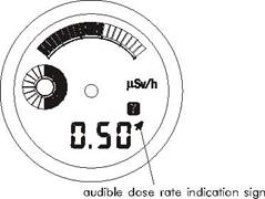 Fig.3.2 At the natural background, the rate at which audible signals repeat is a few signals per minute. It will increase with increasing the gamma-radiation intensity as a result of, for example, approaching to a radiation source. This provides a possibility of searching and locating of gamma-radiation sources. 15
3.2.4 The mode of recording the DER registration history
3.2.4.1 Two short pressings of button 2 (SELECT) switch over from DER value indication to the mode of recording the DER registration history (Fig.3.3). The display will show the number of an expected reading (the cell number where the current DER value will be recorded). The recording of the current DER value is performed by short pressing of button 1 (MODE). The display will show the next number of the memory cell (increased by 1) where the next DER value will be stored. The indication “d - - -“ means that the memory is full, i.e. 500 readings were stored. To store and to view the stored history it is necessary to use the PC communication mode (see clause 3.2.6). The counter of readings may be reset while in the set mode. After the counter is reset (if information in the memory was not transmitted to PC) then each new reading will be stored in the memory instead of the old one. When the history events are recorded in non-volatile memory simultaneously DER, DE values, time (hours, minutes, seconds) and the date (date, month, year) are being recorded as well. 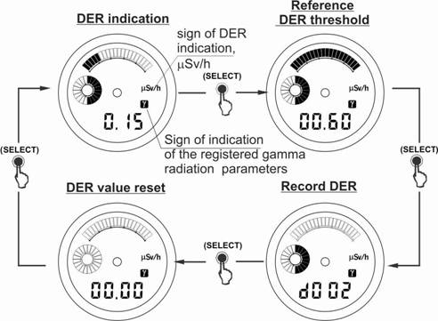 Fig. 3.3 Attention! The mode of recording the DER registration history and DER indication start mode are additional modes. The availability or absence of these modes depends on the user software supplied on CD (3.2.6.4). 16
3.2.5 The DER registration start mode
3.2.5.1 Three short pressings of button 2 (SELECT) switch over from the DER indication to the DER registration start mode (Fig.3.3). The LCD will show non- flashing digits 00.00 Sv/h. To start the DER registration mode press button 1 (MODE). The digits on the LCD will be flashing until the first registered DER value appears. As the indicator is registering the DER value, the flashing circular analogue scale is filling in. The flashing circular analogue scale serves to indicate the DER registration start mode. The empty circular analogue scale corresponds to a statistical error more than 100 %; the completely filled in scale corresponds the statistical error no more than 20 %. To store the registered DER value, use button 1 (MODE). Exit from the mode of DER registration start, exit from the mode of DER registration before the analogue scale is completely filled in, or exit from the mode after the indicated value was stored, is performed by button 2 (SELECT). 3.2.6 The mode of DE threshold reference, DE accumulation time and the PC communication mode 3.2.6.1 The repeated short pressing of button 2 (SELECT) switches from the DE indication mode to the mode of DE threshold reference, to the mode of time indication (in hours) during which the DE value was accumulated in accordance with Fig 3.4. The indicator will automatically return to the DE indication, if the buttons are not used for approximately 5 seconds. ATTENTION! When batteries are replaced the value of accumulated DE and DE accumulation time are stored in the indicator memory. 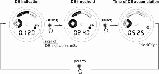 Fig. 3 4 17
3.2.6.2 The indicator allows storing and transmitting to PC through IR communication channel a history of DE and DER registration, events of exceeding the preset DE and DER threshold values, the moment of setting the new time zone using the buttons.
Selection of the history type (linear or circular) and of recording frequency is performed under a special program. The indicator performs the exchange of information with PC under the user software supplied on CD over the communications protocol compatible with IrDA interface. 3.2.6.3 System requirements to PC: - A PC not lower than Pentium III; - 1 GВ free HDD space; - printer and unit for operation with IrDA protocol for the exchange of information with the Dosimeters are necessary for comfort program running; - The program runs under OS Windows 2000/XP/VISTA, Windows 7. 3.2.6.4 For using the indicator in PC communication mode through IR channel it is necessary to: - read the user software supplied on CD; - connect the adapter of IR communication channel to a PC COM port (using the adapter built in a PC shall be permitted); - install the unit of IrDA communication in the system and switch on the IR connection in the mode of searching external IR connection devices; - install the user software supplied on CD to PC; - orient the indicator and adapter of IR communication channel of the PC by placing the indicator at a distance of 10-20 cm from the adapter of IR channel; - switch on PC communication mode by pressing button 3 (LIGHT). With this “PCon” will be indicated on the LCD and the short signal will sound; - perform readout of the indicator's information, following the program's instructions. 18
Exit from PC communication mode is performed by pressing any button or after 10 s if there is no source of IR data nearby. With this the short signal will sound and the indicator switches on the DE indication mode.
Attention! The long stay in the PC communication mode (PCon) decreases the battery service life. 3.2.7 The reference mode allows displaying on the LCD: - the time in hours and minutes when the alarm clock will be turned ON (the alarm clock mode); - the date, the month and the year; - the current time (in minutes and seconds); - the preset DER thresholds ( Sv/h); - the preset DE thresholds (mSv), (see clause 3.2.6.1); - the DE accumulation time (in hours) and allow switching ON/OFF the alarm clock as well. To switch over from the current time indication mode to the reference mode it is necessary to switch on the current time mode as described in clause 3.2.2. Then after short pressing of button 2 (SELECT) the following information is indicated on the LCD in rotation (Fig. 3.5): - the time (in hours and minutes) when the alarm clock will be turned ON; - the date, the month and the year; - the current time (in minutes and seconds). - 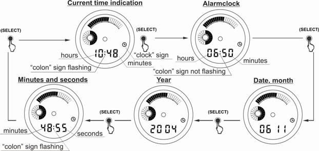 Fig.3 5 The indicator will automatically return from the reference mode to the current time indication mode in approximately 5 seconds. N o t e - To exit from the current time reference in minutes and seconds it is necessary to press button 2 (SELECT) again. 19
Switching ON (OFF) the alarm clock mode is performed by short pressing of button 1 (MODE) when the alarm clock ON time is displayed. In the alarm clock
mode the corresponding sign " The alarm clock signal will sound at the preset time and will be activated for 60 seconds. Stop the sound signal by short pressing of button 2 (SELECT), button 1 (MODE) or button 3 (LIGHT). 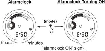 Fig. 3.6 To switch over from the DER indication to the reference mode it is necessary to switch on the DER indication as described in clause 3.2.2. Then after the short pressing of button 2 (SELECT) the preset threshold of DER (in Sv/h) and the filled in linear analogue scale will be displayed on the LCD (Fig.3.7). In approximately 5 seconds the indicator will automatically return to the DER indication. 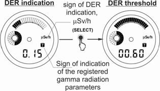 Fig. 3.7 To switch over from the DE indication to the reference mode it is necessary to switch on the DER indication as described in clause 3.2.2. Then after the short pressing of button 2 (SELECT) the preset threshold of DE (in mSv), the filled in circular analogue scale and DE time accumulation (in hours) will be displayed in rotation on the LCD (Fig.3.4). In approximately 5 seconds the indicator will automatically return to the DE indication. Knowledge of the DE accumulation time is of great importance from the point of view of medical and biological consequences for a human organism! (See “Standards of radiation safety”) 20 3.2.8 Set mode 3.2.8.1 In the set mode the user has the following possibilities: - to set the alarm clock ON time and current time; - to set DER threshold; - to set DE thresholds. 3.2.8.2 To set the alarm clock ON time and current time enter the time indication as described in clause 3.2.2. Then the long pressing of button 2 (SELECT) switches on the setting the alarm clock ON time. After this the display will show the flashing hours of the alarm clock setting and the set mode sign - SET (Fig. 3.8). 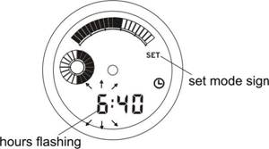 Fig. 3.8 To correct the flashing digit by one press and release button 1(MODE). For setting the minutes, press and release button 2 (SELECT) again. The minutes will be flashing. Pressing of button 1 (MODE) will change the flashing digit by one. So, each short pressing of button 2 (SELECT) will switch the values in rotation shown on Fig.3.9: - hours of setting the alarm clock ON time; - minutes of setting the alarm clock ON time; - seconds of the current time; - minutes of the current time; - hours of the current time; - date; - month's nomber; - year. 21  Fig.3.9 Each short pressing of button 1 (MODE) changes the flashing digit by one. Hold down this button to change the digits rapidly. N o t e - Pressing of button 1 (MODE) when seconds of the current time are flashing will result in their resetting. This allows the electronic watch setting according to time-signals. The indicator will automatically exit from the set mode, if the buttons are not used for approximately 1 minute, or by long pressing of button 2 (SELECT). 3.2.8.3 To set DER threshold switch on DER indication mode according to clause 3.2.2. The long pressing of button 2 (SELECT) switches on the indication of the preset DER threshold on LCD; the two least significant digits (tenths and hundredths of µSv/h) will be flashing, the set mode sign SET will appear and the filled in linear analogue scale will be indicated (Fig. 3.10). 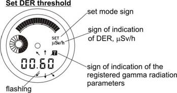 Fig 3.10 Each shot pressing of button 1 (MODE) changes the value by one. The next short pressing of button 2 (SELECT) will make the first two digits before the decimal point flashing on the display (units and tens of µSv/h). Change these digits by pressing button 1 (MODE). The next short pressing of button 2 (SELECT) makes the first two digits flashing on the display (hundreds and thousands of µSv/h), which may be also changed by pressing button 1 (MODE). 22
After the next pressing of button 2 (SELECT) the indicator will enter the state when the counter of history events may be reset. This may be done by pressing button 1 (MODE). The second pressing of the button may cancel the reset of the counter. The indicator will automatically exit from this mode, if the buttons are not used for approximately 1 minute, or by long pressing of button 2 (SELECT).
If the preset DER threshold is exceeded, an audible signal will sound, the indicator will enter the DER indication mode if the other value was displayed, and the LCD will show the completely filled in linear analogue scale. The audible signal will sound until the DER value becomes lower than the preset threshold. The signal may be switched off by pressing button 2 (SELECT), button 1 (MODE) or button 3 (LIGHT). ATTENTION! When the battery is replaced, the DER threshold is not changed. The user may set the DE threshold at his own discretion taking into account the relevant Standards or recommendations of local competent institutions. 3.2.8.4 To set the DE threshold enter the DE indication mode according to clause 3.2.2. Long pressing of button 2 (SELECT) switches on the indication of preset DE threshold on LCD; the two digits (hundredths and thousandths of mSv) will be flashing, the set mode sign SET will appear and the filled in circular analogue scale will be indicated (Fig. 3.11). Every short pressing of button 1 (MODE) will change the value by one. 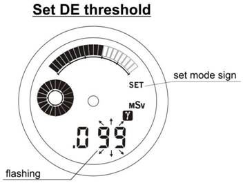 Fig.3.11 The next short pressing of button 2 (SELECT) will make the first digit after the decimal point (tenths of mSv) flashing, its change is made by pressing button 1 (MODE). The next short pressing of button 2 (SELECT) makes the last two digits (units and tens of mSv) flashing on the display, the next pressing makes the first two digits (hundreds and thousands of mSv) flashing, which also 23
may be changed by pressing button 1 (MODE). If button 2 (SELECT) is pressed again the indicator will return to the state when hundredths and thousandths of mSv are flashing.
The indicator will automatically exit from the set mode, if the buttons are not used for approximately 1 minute, or by long pressing of button 2 (SELECT). If the preset DE threshold is exceeded, an audible signal will sound, the indicator will enter the DE indication mode if the other value was indicated, and the LCD will show the completely filled in circular analogue scale. The signal may be switched off by pressing button 2 (SELECT), button 1 (MODE) or button 3 (LIGHT). WARNING! When viewing or setting the DE threshold, please remember that the DE threshold changing may cause the reset of the accumulated DE value and DE accumulation time. It is possible if buttons - activated DE reset is enabled by the program (3.2.6.4). The user may set the DE threshold at his own discretion taking into account the relevant Standards or recommendations of local competent institutions. 3.2.8.5 Measurement of the battery voltage is carried out after replacing the batteries and during operation of the indicator every minute at 00 seconds. In case of the partial battery discharge the LCD will display the message “bAtt” every 10 seconds and the indicator will continue its operation. It is necessary to replace the battery! In case of the critical battery discharge the indicator discontinues the registration, does not respond to controls and the LCD displays the message “bAtt”. 3.2.9 The movement of the analogue watch 3.2.9.1 The hands that are put in motion by the movement of the analogue watch continuously indicate the current time in hours, minutes and seconds. 3.2.9.2 To set the correct time, pull the crown out from its normal position until the click, when the second hand is on the digit 12 (the movement will stop). Turn the crown and set the minute and hour hands at the required starting time. To start the movement at time-signals return the crown to its normal position until the click. The first shift of the second hand will be in a second. 24
4 MAINTENANCE
4.1 Maintenance of the indicator involves the preventive treatment, battery replacement, and regular operation check up (as described in clauses 3.2.1 – 3.2.8). 4.2 The preventive treatment includes the external examination, removing dust, dirt and decontamination of the indicator case if it is contaminated with radioactive dust. Decontamination is performed with a cloth impregnated with ethyl alcohol. 4.3 To replace the battery it is necessary to: - turn off and remove the back cover of the indicator; - take off the contact plate which covers the battery compartment moving a clip with a screw driver; - remove step-by-step the battery of the electronic block of registration. - insert new battery observing the polarity - “+” of the battery should be faced towards the indicator cover for the battery; - place the contact plate covering the battery compartment, place the cover. By short pressing of button 4 (RESET) turn ON the self-test mode; the LCD should display all the segments and the indicator switches over to the DER indication mode. The first DER value of the natural radiation background will be displayed on the LCD in approximately 30 seconds. The current time of the analogue watch is set as described in clause 3.2.9. Attention! For the battery replacement it is recommended to take your indicator to a watch shop. N o t e - It is necessary to take into consideration that the more frequent and longer use of the backlight and audible signals than indicated in clause 2.3.13 will significantly shorten the lifetime of the battery of the electronic block. 4.4 To ensure the water resistance of the indicator it is recommended before placing the cover to clean the sealing ring and its fitting place in the case and to treat them with silicon lubricant. Then screw down the case tight with an appropriate tool and check water resistance using water resistance tester for watches. 4.5 All operative parameters are renewed in the non-volatile memory of the indicator every 10 minutes. Thus the following information is regained after the battery replacement: - the accumulated DE value; - the DE accumulation time; - the DE threshold value; - the DER threshold value; 25
- the value of the counter of history events;
- the date, month, year, hours, tens of minutes; - the alarm clock ON time. When the battery is replaced, the information about history events stored in memory will be safe. After the battery replacement the user needs only to set the accurate time to return the indicator into the initial state. The battery described in clause 2.2 should be used or the similar types. Otherwise the specifications of the indicator are not guaranteed. 26
5 TROUBLESHOOTING
5.1 The list of possible problems and their solutions are specified in table 5.1. Table 5.1
27
6 STORAGE AND SHIPPING
6.1 The indicator in package is to be stored at the air temperature from 0 to + 45 C and humidity up to 95% at the temperature of 40 C. Indicators without package are to be stored at the air temperature from +10 C to 35 C and humidity up to 80 % at the temperature of 25 C. The storage place should be free of dust, vapours of strong chemicals, aggressive gases and other substances that may cause corrosion. Indicators are to be stored without battery if the storage duration is more than 6 months. 6.2 Indicators may be shipped by any kinds of closed transport. When indicators with battery is carried by air, the DER threshold should be set at no less than 100 Sv/h. Indicators in package should be placed in hermetic compartments. When carried by sea, indicators in package should be placed in hermetic plastic bags with silicagel according to GOST 3956-76. When shipping indicators, the environmental conditions should be within the following limits: - air temperature from -50 C to +50 C; - relative humidity up to 100 % at the temperature of + 40 C. 28
7 WARRANTY
7.1 The manufacturer guaranties that the indicator meets the requirements of Technical Conditions provided that the customer will observe the guidelines of its use, shipping and storage described in this manual. 7.2 The warranty period of use is 18 months from the date of sale within the warranty period of storage. 7.3 The warranty period of storage is 6 month since the date of indicator acceptance by the officer of the manufacturer Quality Control Department. 7.4 Warranty and after-warranty repair is carried out by the manufacturer or the institutions that have the manufacturer’s permission. 7.5 Warranty does not cover the indicators: - without the operating manual; - with mechanical damages and if the requirements of exploitation and storage were not satisfied; - after expiration of the warranty period stated in section 7.2. 7.6 The warranty period of use is prolonged for a period of warranty repair. 7.7 The battery replacement is not considered as the warranty repair. 29 (责任编辑:金银工艺品店) |
||||||||||||||||||||||||||||||||||||||||||||||||||||||||||||||||||||||||||||||||||||||||||||||||||||||||||||||||||||||||||||||||||||||||||||||||||||||||||||||||||||||||||||||||||||||||||||||||||||||||||||||||||||||